2. Hardware assembly
The layout
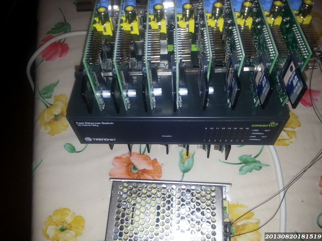
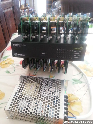
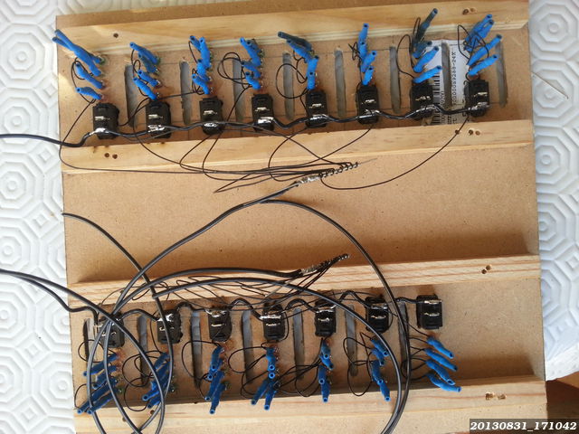
Once I got all the hardware, I had to try to mount everything together. The very first step was to insert all the SD cards in the Raspberry Pi card readers, then to put 7 Raspberry together and 8 Raspberry together to create the 2 raspberry stacks. As I already told in the Hardware choices page, I tried to use wood, but it was not the right solution. I preferred to use PCB-to-PCB standoffs. Of course, it will be a pain if I need to extract the 4th card, but it will be rigid and robust. Then I connected all the network cables to the raspberry. I wanted to have an idea of the final layout. All the cables were OK, the layout seemed fine.
Live test
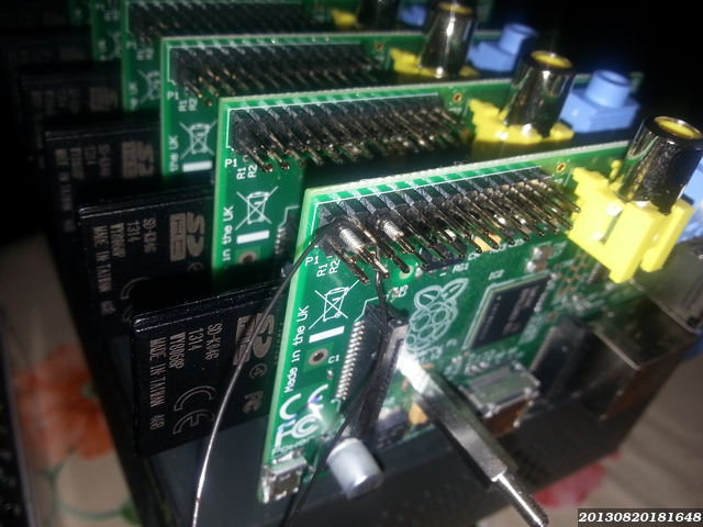
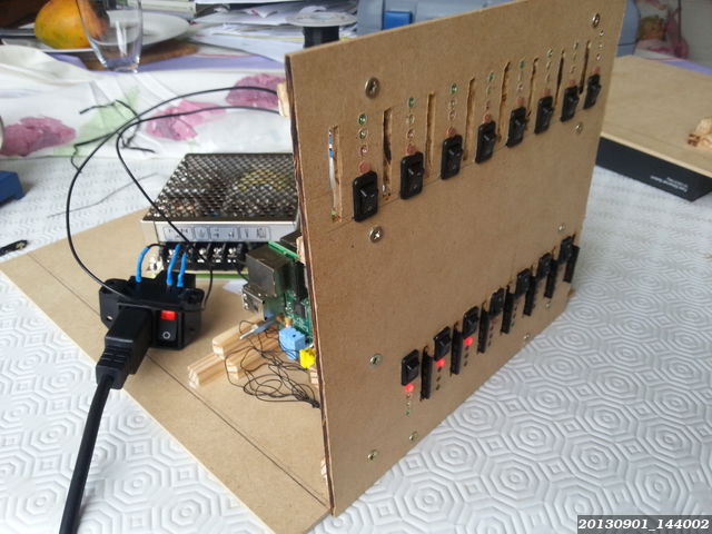
I just had to connect the power supply to test it. It was also the opportunity to make my very first wire-wrapping test. I wrapped 2 cables on the pin P1-02 and P1-06.
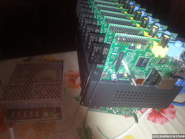
I connected the first one to the positive screw on the power supply, the second one to the negative, and I connected quickly the power supply... The power supply green led lighted up, the raspberry red led also (half won at this step, the card myight not boot for any reason), and the other raspberry leds began to blink... I had a preview of the final cluster with only one node.
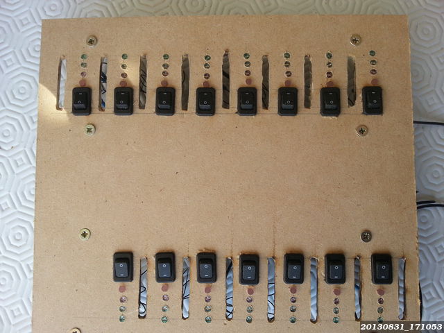
The geek's LEDs
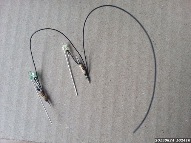
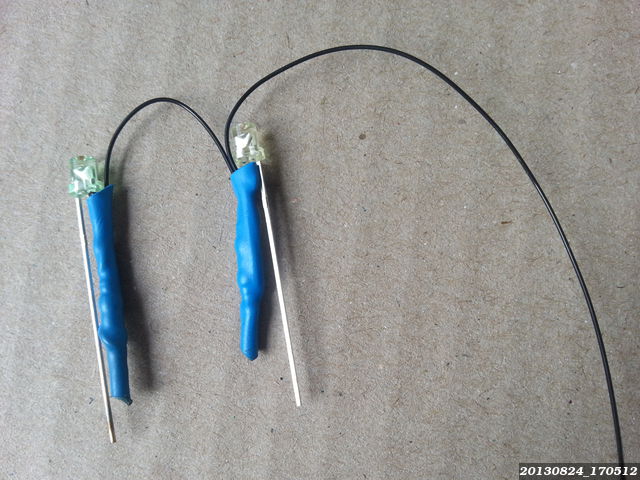
As I wanted to have LEDs connected to the GPIOs and as I wanted to keep the power consumption the lowest possible, I wanted to use the GPIO pins and to be able to disable all the LEDs with a shared switch. I first connected the LEDs with all the anodes connected to the 3.3V (P1-01), and the anodes to the GPIOs 22-23-24 with a 100 Ohms resistor between the cathodes and the GPIOs. It worked, but it was impossible to have one master switch for all the LEDs, my ordered 100 Ohms resistors allow me to use 3.3V only and not 5V from the power supply, I can not use directly a 5V wire with a switch, from the power supply... But I can revert the problem, the GPIOs wont be the negative, but the positive and I will be able to use the negative from the power supply, with a LED switch... Now that I know how to connect, I had to prepare the LEDs to make them more robust and shortcut proof. I chose to wire-wrap the resistors on the cathodes, before the common negative and to secure the connections using an Heat-Shrinkable tube (I ordered other red LEDs and was still waiting for them when I took these pictures) :
The case
Theoric design
The wood was not a good idea to create the nodes stacks, but it can be used as a skeleton for the case. Here is a Blender3D mockup of this skeleton :
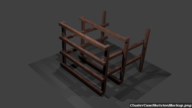
I want to have the SD cards available from the front panel. I wanted to have a compact layout, so I bought 15cm network cables. It means that the HDMI connectors wont be available, but that the case will have to be larger because of the composite connectors. I have to place stops at the front and the back of the cards to be able to push/pull the SD cards, but I can not have a stop at the bottom/back because of the network connector. I chose to use directly MDF panels and to screw wood sticks on the panels (I had to buy a Dremel case for this, but I wont count it in the bill ! )
There are two horizontal wood sticks on the front panel to : lock the switch in front of its window and to lock the Raspberry Pis 1cm behind the front panel (to keep enough place for the switch, the LEDs and to have only half of the SD cards outside of the case). Then, I used one stick at the very top and at the very bottom to lock the Raspberry Pi too. Then, I'll make holes in front of each node : SD card slot, 3 LEDs (maybe 4), and the node switch.
The reality
After several tests, I chose to build the case using MDF (Medium Density Fiberboards) and to screw/glue wood sticks inside. It was easier and faster to design the case and to fix design issues. For example, after building the floor, roof and front panels, the cluster began to heat... Adding heat sinks would not have solve the issue. The issue was that the air was not moving inside the case, even with 3 missing panels ! I had to force air flows and to create escapes for the hot air. The hot air was staying inside because of... convection ! What a terrible design issue ! So, I first created escapes for the hot air and waited to see the result. The goal was to keep the 15 CPUs and the switch below 80°C. If needed, I can change the case orientation to make the air flow easier and finally, I can add the biggest possible fan (big mean slower for the same air flow, and slower means more quiet).