Internal symetrical power supply
After a first failure (Discarded power supply with virtual ground), I decided to use a dual-coil transformer wit three regular voltage regulators. Thus, I redesigned the rectifier part and the regulation part.
Rectification

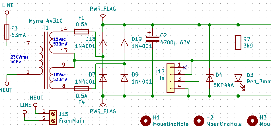
I need to generate -12V and +12V, the regulators need at least 2V more on their input than on their output, thus I'd need 14Vdc in both directions. The filtering capacitor can not be infinite, I sized it to have no more than 2.4V peak-to-peak after rectification, thus I'd need to have 16V redressed. The each diode in the bridge has a forward voltage of 1V and the current goes through 2 of them, ok, I need 18Vac peak-to-peak. This means 18/1.41=12.8Vrms. I could choose a dual 12V coils transformer but I would be at the limit and I would need to use a bigger filtering capacitor. I found a good candidate with two 15V coils, which will be perfect.
Each coil will produce 15Vrms and can sustain 0.533A. I joined the coils to have a big 30Vac 533mA coil with a central point. This central point is my ground, each end of the coil produce 15Vac with 180° of phase difference (the voltage of one is the opposite of the other). This goes through a rectifier diode bridge. I chose 1N4001, they can handle 1A and 50Vpp, 30Vac means 42Vpp. Depending on the manufacturer, the forward voltage is between 1V and 1.1V. The current will loose 2.2Vpp max when going through this bridge.
I used a first big capacitor as a first level of filtering. It had to support 30Vac (42Vpp), I chose 63V. And I used the formula C=I.T/Vdrop to calculate its capacity. C is the capacitor value in Farad, I is the maximum current drawn in Ampères, T is the period time in seconds, and Vdrop is the maximum acceptable voltage drop. I=500mA, the main frequency is 50Hz in France, this means 100Hz after rectification, thus T=0.01s, The regulators input need to be approximately 3V over their output, meaning 15V. I need a clean 30Vdc here. Despite I could accept 10V drop, I oversized to have 1V drop and I'll have a good clean current to feed the regulators. Given that this capacitor is oversized and that I will have extra capacitors behind, I chose the closest smaller standardized value : 4700µF. In theory, if the project draws 533mA, the voltage should remain between 42.30Vac and 41.41Vac, 30Vrms and 29.38Vrms, which is more than acceptable. The important thing here is to have a 63V capacitor minimum.
I decided to add a connector for two reasons :- providing externally providing power
- testing the quality of the power with probes.
I'm human, our world is not perfect and I can make mistakes, I added a TVS (D4) to protect against reversed polarity and overvoltage peaks. Finally, I like to know when each circuit stage is healthy, thus I added a power status LED (D3) with a current limiting resistor (R7). The resistor is sized to limit the current to 10mA, this tradeoff should be enough to be visible but not consuming to much.
Regulation
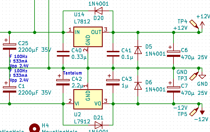
At the very begining of the regulation, I added filtering capacitors to polish the initial filtering. I chose two smller capacitors sized to filter the rectification bridge frequency under 533mA : 2200µF. At the end, the voltage should be very stable, at 40Vdc. These capacitors need to be 35V minimum. They will have to manage 20Vdc.
-12V/+12V

I designed the -12V/GND/+12V schema using the very standard and well known LM7812/LM7912 regulator pair and I followed the applications notes and recommendations from the datasheets (need to read carefully the 7805 7812 7824, 7905, 7912, 7924 datasheet from different manufacturers). I added a flyback diode on each regulator (D20/D21) to protect the regulators against capacitor discharge when switching off. I also added output capacitors (C6/C7) to filter any remaining noise and to help the regulators in case of current peak. These capacitors have to manage 12Vdc and I chose to use 25V capacitors for safety. I needed to add flyback diodes (D5/D6) to protect the regulators from these capacitors.
5V

This design is nearly the same with some adjustments.
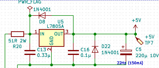
First, I did not use the regulated +12V to generate the 5V, this would make the 7812 work more than the 7912. I prefered to have a bigger drop to 5V from the 20V source. In order to save some dissipation, I used a power resistor (R20) in front of the LM7805. The LM7805 has to provide 5V from 20V, for 150mA (I approximately know the project consumption), it needs 8V to operate. The resistor has to drop 12V when drawing 150mA. I could use 80R (12/0.150) and it would dissipate 1.8W (80*0.150²) but I prefer to be careful in case of current peak, in case of 200ma, the resistor would have to dissipate 3.2W and I prefered to remain under 2W resistors. 51R semt to be a good tradeoff : in case of current peak (200mA), it would drop 10V (within the regulators limits and only .75W remaining to dissipate by the regulator) and dissipate 1.56W, under normal current (150mA), it will drop 7.6V and dissipate 1.14W.
Of course, 5V regulation also have a flyback diode (D8), a buffer capacitor (C5) and a regulator protection diode (D22) against C5.
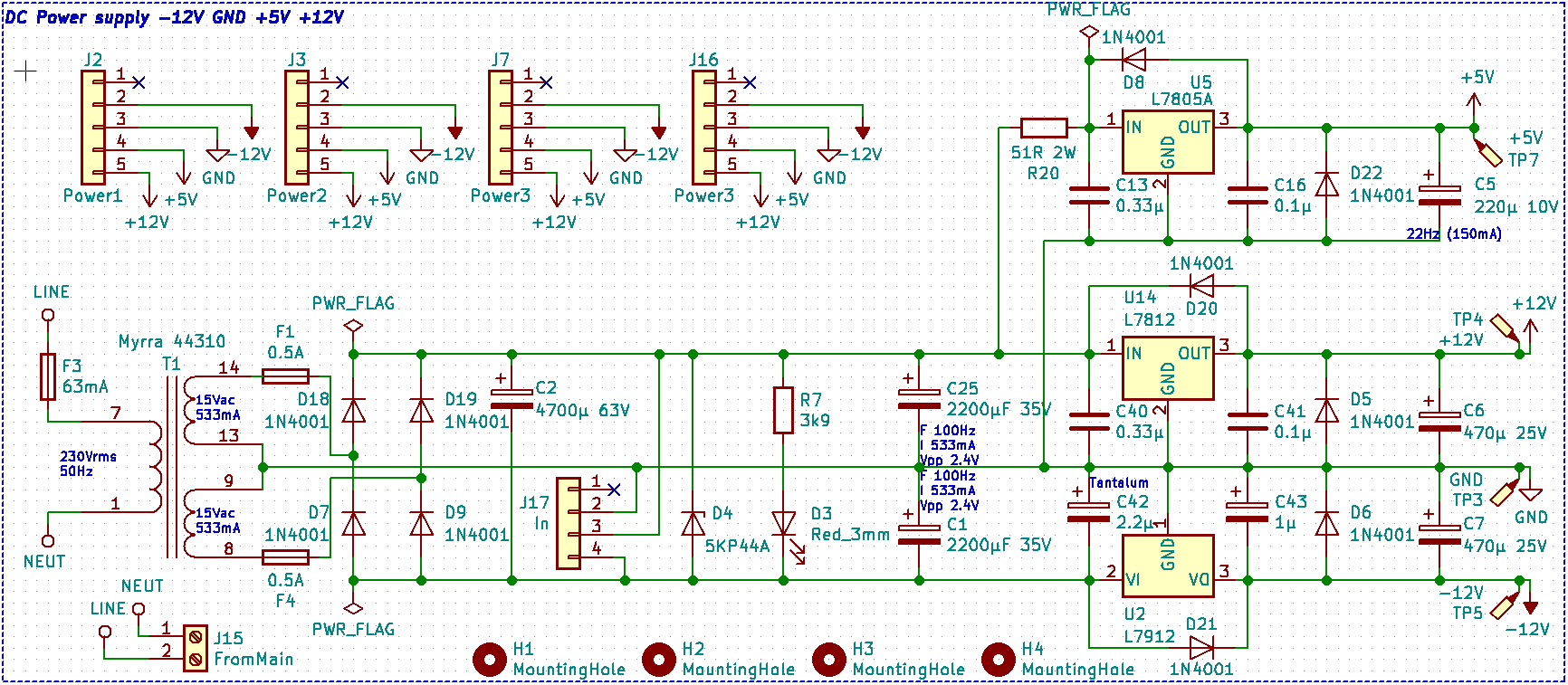
Full schema
